Halo Light
Learning how to install led neon flex for signage requires more than attaching glowing tubing to a wall. A reliable installation begins with accurate measurements, suitable materials, and careful electrical planning. The sign’s shape, viewing distance, mounting surface, and outdoor exposure all affect the final result. Small mistakes can create visible shadows, uneven brightness, or premature failure.
This guide introduces ten practical tips used by experienced signage installers. You will learn how to inspect the LED neon flex, choose the correct power supply, prepare aluminum channels, and respect the product’s minimum bend radius. Clean surfaces matter. So does drainage. Outdoor signs need suitable sealing, cable protection, and an appropriate IP rating confirmed by the manufacturer. Always disconnect power during wiring, and ask a qualified electrician to verify mains connections.
Details make the difference.
A smooth silicone jacket may look flexible, but it can still kink when forced around a tight corner. Cutting at the wrong mark can also damage an entire section. I have found that dry-fitting the letters before applying adhesive prevents many avoidable corrections. Yet adhesive alone is not always enough, especially on dusty brick or warm metal. Clips, channels, and mechanical supports may provide better long-term stability. These recommendations follow common professional practice, but every product behaves differently. Read its installation sheet carefully, test the lighting before final mounting, and allow time to question your assumptions. A slightly slower installation often produces a cleaner, safer, and more dependable sign.
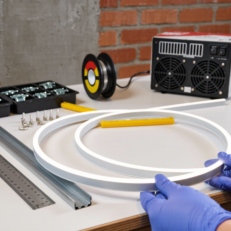
Before installing LED neon flex, inspect the signage surface under normal daylight. Check whether it is brick, painted metal, acrylic, wood, or glass. Each material changes the fixing method and cable route. Dust, grease, peeling paint, and moisture can weaken adhesion. Wipe a small test area first. A clean surface matters. Also check for drainage, sharp edges, and heat sources. Outdoor panels need weather-resistant routing and protected connections. Measure the sign panel, not only its outer frame. Record curves, corners, mounting holes, and nearby power access.
Draw the design at full scale on paper or in a digital layout. Mark the centerline and every change in direction. Keep bends smooth, and never force the flex into sharp corners. A cardboard template can reveal spacing errors before drilling. Leave enough room for connectors and maintenance access. Do not hide the power supply behind a sealed panel. That mistake is easy to make. Confirm the mounting surface can support the channels, clips, and cable weight. Follow the product instructions and applicable electrical requirements.
Plan the starting point near the power entry, then trace the most visible edge. Use a scale drawing to estimate total length and account for offcuts. Keep letter spacing consistent, especially around narrow characters. Check the layout from the viewer’s distance, not only up close. Stand several meters away. Uneven gaps become obvious there. Before final fixing, photograph the dry layout and review it with another person. A second opinion may expose a crooked baseline, awkward shadow, or cable path that seemed acceptable during installation.
Choosing compatible LED neon flex, power supplies, and mounting accessories determines whether a sign stays bright and reliable. Check the flex’s voltage, wattage per metre, colour temperature, IP rating, and minimum bending radius. Never connect 12-volt flex to a 24-volt supply. That mistake can destroy a full installation quickly.
Allow at least 20% spare capacity in the power supply. For example, 10 metres at 12 watts per metre requires 120 watts; select a supply rated near 150 watts. Confirm output voltage, dimming compatibility, ventilation, and connector polarity. The U.S. Department of Energy’s 2023 Solid-State Lighting R&D Opportunities report identifies efficacy and thermal control as continuing performance priorities. Heat still shortens component life, especially inside shallow sign cabinets. Use aluminium mounting channels where possible. They improve alignment and help dissipate heat. Small clips alone may sag on long curves.
Mounting hardware must match the surface. Use stainless screws outdoors, sealed connectors in exposed areas, and channels that fit the flex profile. IEC 60529 provides the IP protection framework, but an IP rating does not replace correct installation. I have seen outdoor signs fail because water entered an unsealed end cap. It looked secure. It was not. Leave access for testing and replacement, and keep cable runs short to reduce voltage drop. The IEA’s Energy Efficiency 2024 report continues to identify LED lighting as a major efficiency opportunity, but efficient products still need correct installation. Review the layout twice. Bends are rarely as forgiving as drawings suggest.
Select compatible LED neon flex, power supplies, and mounting accessories before installation.
These percentages represent practical design targets: keep the power supply at or below 80% of its rated capacity, allow approximately 20% spare capacity, limit voltage drop to about 3%, and complete all safety, polarity, sealing, mounting, and testing checks before energizing. Always confirm the exact voltage, bend radius, IP rating, wattage, and accessory requirements in the product datasheet.
Accurate measuring makes LED neon flex signage look clean and prevents expensive waste. Measure the channel or sign outline twice, including every corner and return. Record each section separately instead of relying on one total length. Leave a small service allowance near the power connection, but avoid loose loops behind the sign. Check the flex’s bending direction before marking it. Some products bend only sideways, not forward. A wrong assumption can damage the internal circuit.
Tip: Use a flexible tape for curves and a rigid ruler for straight runs. Mark the cutting point with a fine pen. Cut only at the printed cutting marks, usually spaced along the flex. A sharp, clean blade creates a flatter end. Do not crush the silicone housing. Keep the cut piece nearby until the installation is tested; it can reveal a measuring mistake.
Before mounting, inspect every end for exposed conductors, uneven cuts, or moisture. Prepare connectors, end caps, mounting clips, and the correct power supply on a dry work surface. Test the measured section briefly before applying adhesive or permanent clips. I once skipped this check and had to remove a carefully aligned corner. It was avoidable. Leave enough room for gentle bends, because forcing a tight turn may create dark spots or stress the housing. Follow the product’s electrical instructions, and disconnect power before making any wiring changes.
| No. | Installation Tip | Recommended Measurement or Specification | Preparation and Installation Action | Verification Check |
|---|---|---|---|---|
| 1 | Confirm the sign dimensions | Measure the actual route in millimetres, including corners, returns, and gaps. | Create a simple drawing and record each straight section and bend. Add approximately 5–10% planning allowance before ordering material. | The total planned length is longer than the measured route but remains within the available reel length. |
| 2 | Check the flex profile | Record the profile width, height, viewing direction, voltage, and rated power from the product specification. | Make sure the channel, mounting clips, end caps, and power supply are compatible with the selected profile. | The flex fits the mounting hardware without compression, twisting, or excessive side pressure. |
| 3 | Identify the cutting points | Cut only at the manufacturer-marked intervals, commonly 25 mm, 50 mm, or another specified pitch. | Use a ruler to transfer the required length to the nearest permitted cut mark. Do not cut between marks. | The mark is clearly visible and the planned cut length matches an approved cutting interval. |
| 4 | Use the correct cutting tools | Use a sharp craft knife or fine-tooth cutter suitable for the profile, plus a ruler and marker. | Disconnect power, support the flex on a clean surface, and make one controlled cut perpendicular to the strip. | The cut is straight, clean, and free from crushed silicone or exposed conductors. |
| 5 | Plan the power-feed location | Place the feed near the centre of long runs when practical; follow the product limit for maximum continuous length. | Minimize cable distance and plan access for the power supply, controller, and maintenance connections. | The feed point is accessible and no run exceeds the specified continuous-length limit. |
| 6 | Calculate the power requirement | Power requirement = installed length × rated watts per metre. Select a power supply with about 20% spare capacity. | For example, a 5 m installation rated at 10 W/m requires 50 W; a supply of approximately 60 W or more provides operating headroom. | Voltage and wattage match the flex specification, and the supply is not loaded at 100% continuously. |
| 7 | Respect the minimum bend radius | Use the minimum horizontal and vertical bend radius stated for the profile; never force a sharper curve. | Mark curves on the template and bend gradually. Avoid folding, kinking, stretching, or twisting the flex. | The diffuser remains smooth, with no visible crease, stress mark, or uneven light output. |
| 8 | Prepare the mounting surface | The surface should be clean, dry, smooth, and free of oil, dust, loose paint, and sharp edges. | Clean the route with a compatible non-residue cleaner. Install mounting channels or clips at regular intervals appropriate to the profile. | The mounting surface is stable and the hardware is aligned before the flex is pressed into place. |
| 9 | Seal and protect every cut end | Use the correct end cap, connector, gasket, or sealant for the product’s indoor or outdoor rating. | Keep sealant away from the LED surface and allow it to cure according to the sealant instructions before energizing. | No conductor is exposed, and the end seal is secure without gaps or loose material. |
| 10 | Test before final installation | Perform a low-risk test before permanently fixing the complete sign assembly. | Check polarity, brightness, colour consistency, connections, heat, and controller operation. Disconnect power before making adjustments. | The entire run illuminates evenly with no flicker, dark sections, abnormal heat, or loose connections. |
Important: Always follow the specific product installation instructions, electrical code requirements, voltage limits, cutting intervals, bend radii, and ingress-protection guidance supplied with the LED neon flex.
Mounting LED Neon Flex correctly starts with a clean, rigid surface. Remove dust, grease, and loose paint before positioning the channel or mounting clips. Keep the light straight around corners; forcing a tight bend can damage internal conductors. Follow the manufacturer’s minimum bend radius, even when the silicone appears flexible.
Cut only at marked points, then inspect the copper pads under bright light. Use connectors rated for the installation’s voltage, current, and weather exposure. A loose connection may flicker before it fails completely. Seal outdoor joints with suitable heat-shrink tubing or a certified enclosure. The connection should not carry mechanical weight. Support the cable separately.
The U.S. Department of Energy reports that LED products can use at least 75% less energy and last up to 25 times longer than incandescent lighting (Energy Saver, “LED Light Bulbs”). That efficiency still depends on proper heat management and electrical installation. I recheck polarity and strain relief twice. It feels excessive. It prevents avoidable callbacks. Apply power briefly before final sealing, because correcting a hidden fault later means removing finished sections. UL 2108 and IEC 60598 guidance also reinforce the need for suitable enclosures, insulation, and protection against moisture. A neat joint is not automatically a safe joint. Test it. Document the voltage, connection points, and final inspection for future maintenance.
Before fixing LED neon flex to a sign, inspect the surface, mounting channel, connectors, and cable path. The surface should be clean, dry, and free from sharp edges. Measure twice. Keep the bending radius within the supplied technical specification to prevent internal damage. I usually connect a short section temporarily before completing the full layout. Test every section. Check for flicker, dark spots, uneven color, loose joints, and unexpected voltage drop. A simple visual check can miss a weak connection, so qualified installers should also verify polarity and output voltage with suitable test equipment.
Heat management affects brightness and service life. Use an aluminum channel where the design allows it, because metal helps transfer heat away from the flexible strip. Do not press the neon flex tightly against insulation or seal it inside an unventilated cavity. Run the lighting for 10 to 15 minutes, then check the surface temperature according to the product instructions. Warm is normal. Excessive heat is not. I once treated ventilation as a minor detail, and that assumption required reworking the sign.
Complete the installation by securing cables, protecting entry points, and fitting end caps firmly. Keep power supplies accessible for inspection and maintenance. Confirm that all joints are dry and mechanically supported before closing the sign. Check alignment from several viewing distances, not only from the ladder. Record the final circuit layout and test results. A rushed final check can leave one dim section hidden behind a letter. Allow time for that inspection.
Match the supply voltage to the flex voltage exactly. Never connect 12-volt flex to 24 volts. Calculate total wattage by multiplying metres by watts per metre. Ten metres at 12 watts needs 120 watts. Choose a supply near 150 watts.
Keep at least 20% spare capacity for stable operation and future stress. An undersized supply may overheat, flicker, or fail early. More capacity is safer. Verify dimming compatibility and ventilation too.
Check voltage, wattage, colour temperature, IP rating, and minimum bend radius. Confirm the channel fits the flex profile. Clean dust, grease, and loose paint from the surface. A rigid surface matters.
Use aluminium mounting channels when possible. They keep the light aligned and help remove heat. Avoid sealing hot components inside shallow cabinets. Heat quietly shortens component life.
Follow the stated minimum bend radius. Do not force tight corners, even when the silicone feels soft. Cut only at marked points. Inspect the copper pads under bright light.
Use sealed connectors, suitable heat-shrink tubing, or certified enclosures. Match connectors to the voltage, current, and weather exposure. Seal every end cap carefully. Water finds small gaps.
Keep cable runs short to reduce voltage drop. Support the cable separately from the connection. The joint should not carry mechanical weight. Add strain relief and check polarity twice.
Yes. Apply power briefly before sealing hidden joints or finished sections. Check brightness, flickering, polarity, and connection points. A neat joint is not automatically safe. I still recheck everything. It feels excessive, but it prevents avoidable repairs.
Record the voltage, cable routes, connection points, and final inspection results. Leave access for testing and replacement. Drawings can make bends look easier than they are. Review the layout twice.
Installing LED neon flex for signage begins with careful planning. Assess the sign surface, identify mounting points, and map the layout so the lighting follows the intended shape smoothly and evenly. Select LED neon flex with suitable voltage, brightness, color, and weather resistance, then match it with a compatible power supply, connectors, clips, channels, and other mounting accessories. Before installation, measure the planned sections accurately, cut only at marked points, seal exposed ends when necessary, and prepare all components for a clean assembly.
The next step in how to install led neon flex for signage is securing the lighting firmly without creating sharp bends or excessive pressure. Use suitable mounting hardware, guide the flex neatly around corners, and keep electrical connections protected and properly insulated. After mounting, test the entire system for consistent brightness, flickering, loose connections, and correct polarity. Allow adequate ventilation around the power supply, manage heat buildup, and finish the signage by concealing wires, checking alignment, and confirming that every section is stable, safe, and visually consistent.
